The Radar Remote Sensing Group at the University of Cape Town
Geoscience and Remote Sensing Newsletter
Issue #116, pp. 6-12, September 2000.
M.R. Inggs
Department of Electrical Engineering,
University of Cape Town,
South Africa, Private Bag,
7701 Rondebosch,
http://www.rrsg.uct.ac.za/
email: mikings@eng.uct.ac.za
1. Introduction
The Radar Remote Sensing Group (RRSG) [27]
at the University of Cape Town (UCT) has been operating since 1988.
The group, which is headed by Prof. M.R. Inggs, currently comprises 8 MSc.
students, 2 PhD students and 5 research assistants. Funding is received
entirely by way of contract research from industry and postgraduate busaries
from the National Research Foundation (NRF), formerly known as the
Foundation
for Research Development (FRD).
The aims of the RRSG are to develop advanced sensors and techniques/applications
utilising radar technology for the user community. This is seen as an iterative
process, which involves the radar technology experts as well as the users.
Part of this process is the provision of education to the user community
so as to give them a level of understanding of radar technology which will
allow them to utilise the technology efficiently in their own fields of
expertise.
In addition, the RRSG sees itself as a technology consulting group which
can support the remote sensing community in terms of the underlying signal
and image processing technology (hardware and software) utilised in their
specialisations.
2. VHF SAR Sensor
In conjunction with the Council for Scientific and Industrial Research
(CSIR, Defencetek Division) and Reunert Radar Systems, the RRSG
has been involved with the development of the South African SAR
(SASAR) system, originally planned to be airborne during 1995 [16].
However, due to a combination of late delivery of commercial hardware and
flight clearance requirements for the large VHF antenna structure, the
first radiating flights ocurred early in 1999. Although originally designed
for installation on a Boeing 707 aircraft, the system is now fitted to
a turboprop variant of the DC3 (Dakota) aircraft of the South African
Air Force (SAAF). The antenna elements are mounted directly to the
skin of the aircraft.
The SASAR system operates in the VHF-band at 141 MHz with a bandwidth
of 12 MHz. Funding for the system development has been provided by the
South
African National Defence Force (SANDF) Defence Research and Development
Board (DRDB), and the system is managed by the CSIR. All the signal
processing is performed at UCT.
2.1 Signal Processing
The signal processing for the SASAR system is performed using the G2 SAR
Processor, developed over a number of years at the UCT RRSG. This fully
motion-compensated, airborne SAR processor is based on the range-Doppler
algorithm with the main modules written in C, and using Python as the glue
language. Some preliminary processing results are available on-line.
Analysis and simulation has shown that the range-Doppler approach provides
good quality imagery for the modest resolution requirements of the current
SASAR VHF system [13].
In addition, an efficient extension to range-Doppler processing has been
developed [11],
[10],
which allows for higher resolution processing at VHF, although this is
not required for operational use of the current system. Other approaches
suitable to high-resolution, low-frequency processing include the range
migration approach and the time-domain approaches traditionally requiring
more computation, but allowing for a more natural wide-beam motion compensation
implementation.
When processing multiple images with the G2 processor, efficient use
is made of a parallel cluster, which uses the Mosix extension of the Linux
kernel. This cluster is further described in Section 5.
In addition, efforts are underway to produce a parallel version of the
G2 processor using Parallel Virtual Machine (PVM), which will speed
up the processing of individual SASAR images.
2.2 Interference Suppression
Radio frequency interference (RFI) is a significant problem for
SAR systems operating at VHF/UHF-band, because the spectrum is already
used extensively by other services such as television, mobile communications,
radio and cellular phones. Experience with the SASAR system has shown that
even in remote locations the interference power often exceeds receiver
noise by many dB, becoming the limiting factor on system sensitivity and
severely degrading the image quality. Both the notch filter and the LMS
adaptive filter have been applied successfully on RFI contaminated images.
The improvement in image quality was often remarkable, as can be seen in
Figure 1. Furthermore, the LMS adaptive filter was re-written in terms
of its equivalent transfer function, which facilitated efficient integration
with the range-Doppler algorithm [24].
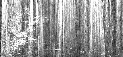
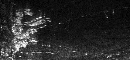
Figure 1: SASAR VHF-band image of the vicinity of Upington, South
Africa, contaminated with RFI (top) and cleaned with the LMS adaptive filter
(bottom). The flight path is along the horizontal axis, with near range
towards the bottom of the image.
2.3 Motion Compensation
Motion compensation is a very important part of the image reconstruction
of an airborne SAR system. On-board inertial measurements can contain significant
drifts over the long synthetic aperture length and differential GPS measurements
may not be of sufficient accuracy. The techniques currently employed by
the RRSG for flight path reconstruction for the SASAR system are described
in [12].
It was found that reconstructing the flight path from a combination of
``smooth'' accelerometer-derived inertial data and ``stepped'' differential
GPS data provided sufficient accuracy for at least first-order motion compensation.
Autofocus techniques have been applied subsequently to fine-tune the motion
compensation.
2.4 Semi Desert and Forest Measurements
The polarimetric VHF SASAR system has been flown over two different terrain
types, namely a flat semi-desert area near the town of Upington (see Figure
1), South Africa, and also over a mountainous, forested coastal area near
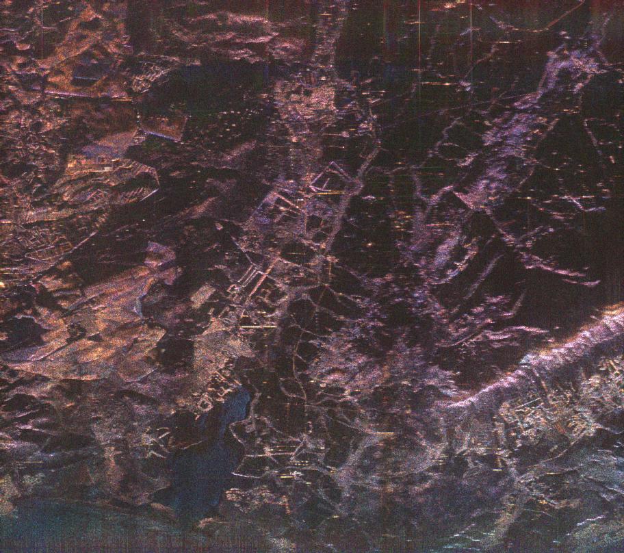
the town of Hermanus (see Figure 2), also in South Africa [14].
It was found that the flat, unvegetated desert terrain provides almost
no backscattered signal for larger incidence angles, but that man-made
targets such as fences show up very brightly. For the coastal scene, it
was observed that large returns from heavily vegetated areas over the entire
range extent were obtained, with many features of interest. The mountainous
area revealed that only the steepest mountain slopes provide significant
backscatter, which implies that forest biomass measurements in this type
of terrain look promising.
Another application which shows promise in heavily vegetated areas is
interferometric mapping of the ground layer (as if the vegetation has been
stripped).
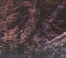
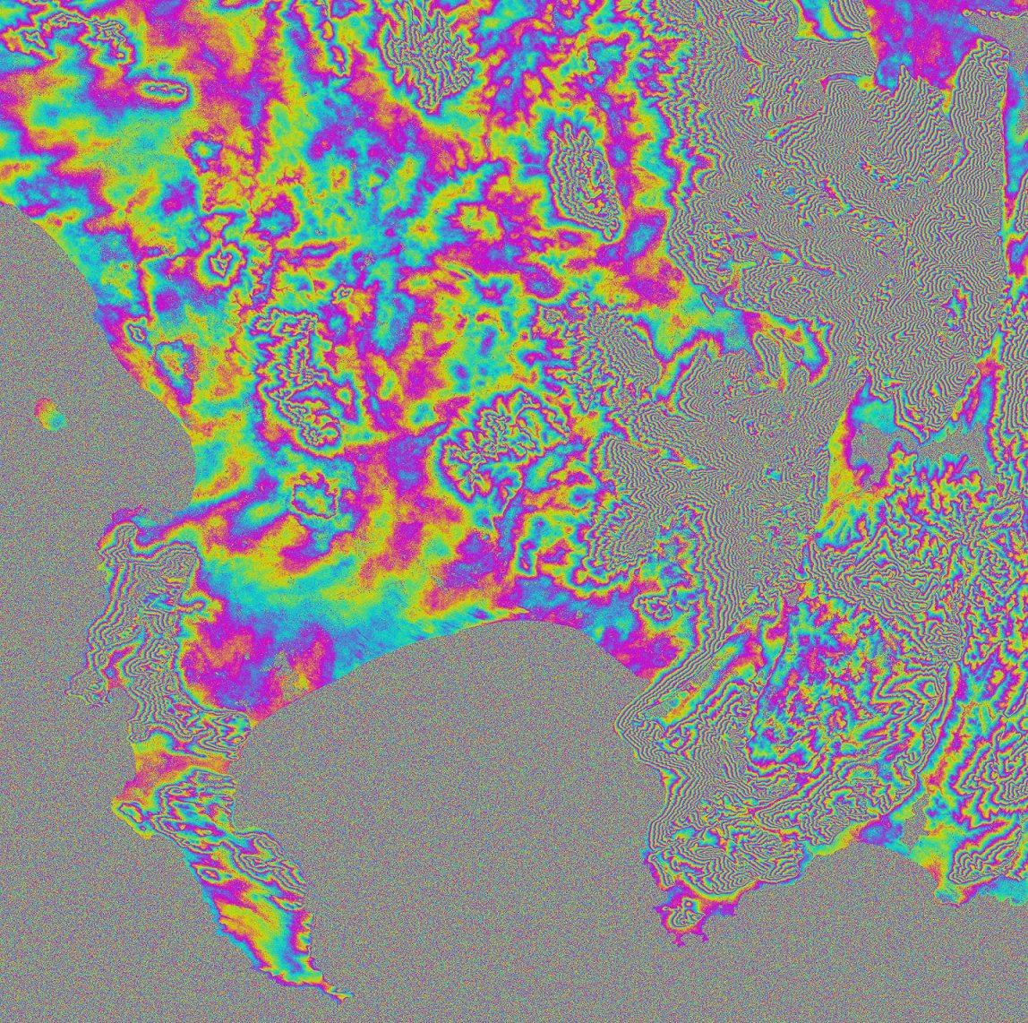
Figure 2: SASAR VHF composite image of Hermanus (Botrivier) area
(HH, VH and VV polarizations). The image azimuth extent is 22.9 km (increasing
from right to left) and the slant range extent is 22.4 km (increasing from
bottom to top). The vertical lines at the top are an artifact of the interference
filter used.
2.5 Repeat-Pass Interferometry
Figure 3 shows preliminary repeat-pass interferometric results which were
obtained from the SASAR sensor [31].
From left to right, Figure 3 shows:
-
One of the two cleaned magnitude images of the Hermanus area, which were
separated by a vertical baseline of about 100 m.
-
The relevant correlation image. A high degree of coherence is visible,
corresponding to the bright regions of the magnitude image.
-
Interferogram.
-
Flattened interferogram.
When comparing the flattened interferogram with the magnitude image, a
correlation between the fringe pattern and the region's topography is already
apparent. However, more work needs to be conducted with the generation
and interpretation of these interferograms. Improvements to the image registration
algorithm should improve the results. Note also that no correction has
been made in these images for the tracks not being accurately parallel.
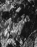

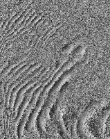

Figure 3: SASAR Hermanus interferogram.
3. Applications of Interferometric SAR
A large number of applications of InSAR have developed over the last five
years, and one focus of the RRSG is to introduce the potential of InSAR
to the local remote sensing community. The following sections describe
some of the projects which are being planned or are underway.
3.1 Measuring the Deflection of the Earth's
Crust

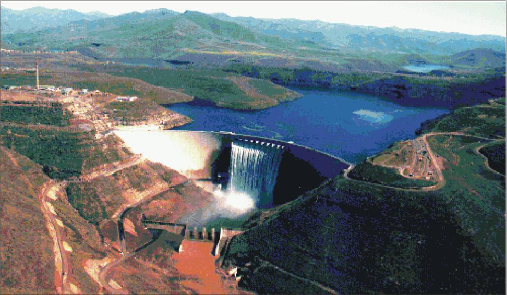
Figure 4: 185 m concrete arch Katse dam.
Work past and current includes an attempt at applying differential InSAR
to the mapping of ground deformation induced by the loading effect of a
large reservoir [25],
[7],
[6].
The filling of the
Katse
Dam in Lesotho, shown in Figure 4, seemed like an ideal opportunity
to measure the deflection of the Earth's crust using InSAR. However, a
positive outcome for this project was hampered by less than anticipated
ground subsidence, and the effects of high relief on otherwise excellent
ERS data.
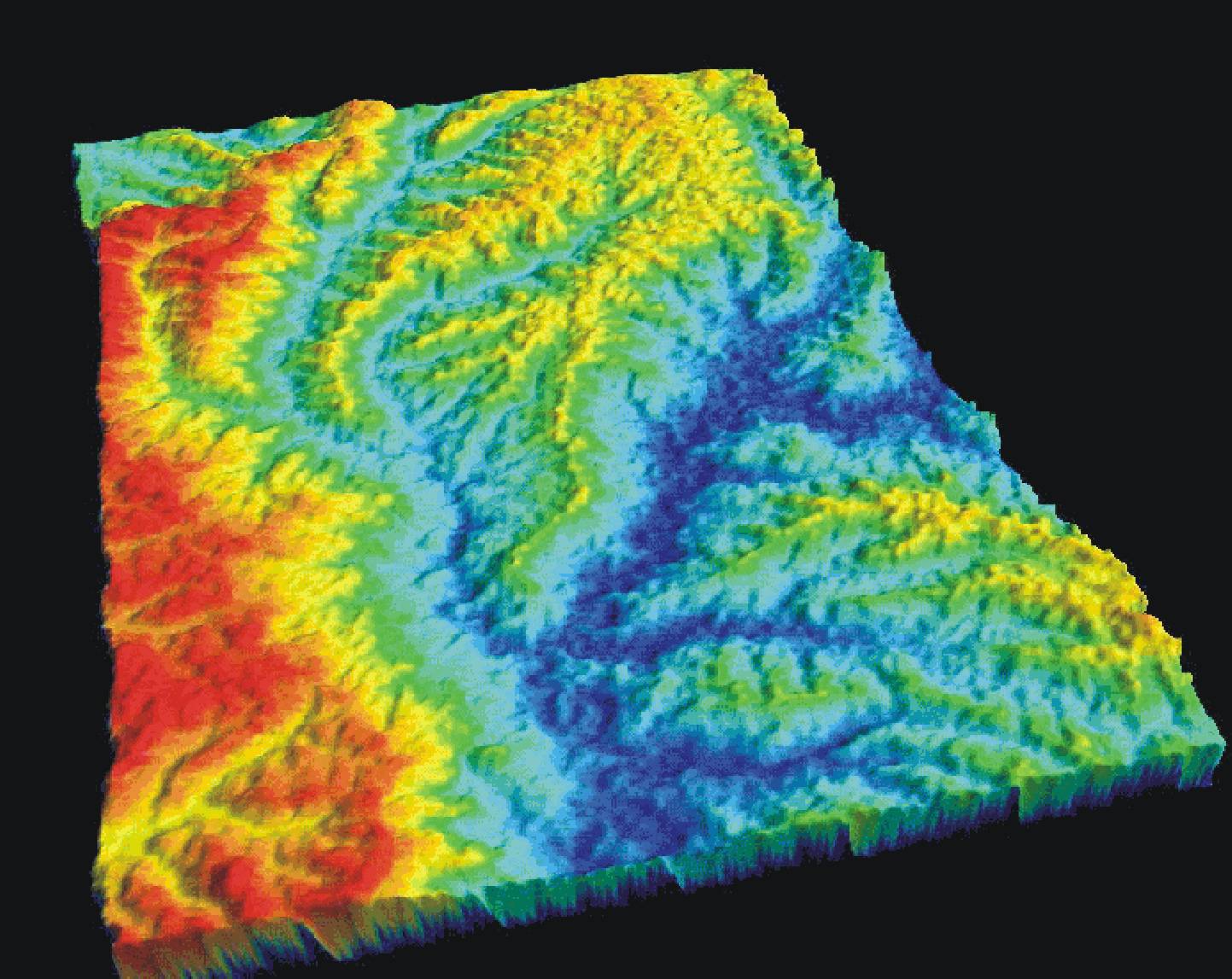
Figure 5: Stereo ERS derived digital elevation model of part of Lesotho.
Because of the high relief, phase unwrapping of ERS Tandem interferograms
was not sufficiently reliable for the production of a digital elevation
model (DEM) for the removal of topographic fringes from the differential
interferograms. Since a viable alternative was not available for this purpose,
we used a pair of overlapping ( » 40 km
baseline) ERS images to stereogrammetrically generate a DEM of a portion
of Lesotho, shown in Figure 5. Although the product was a little noisy,
and required bulk shift corrections, it was adequate for the removal of
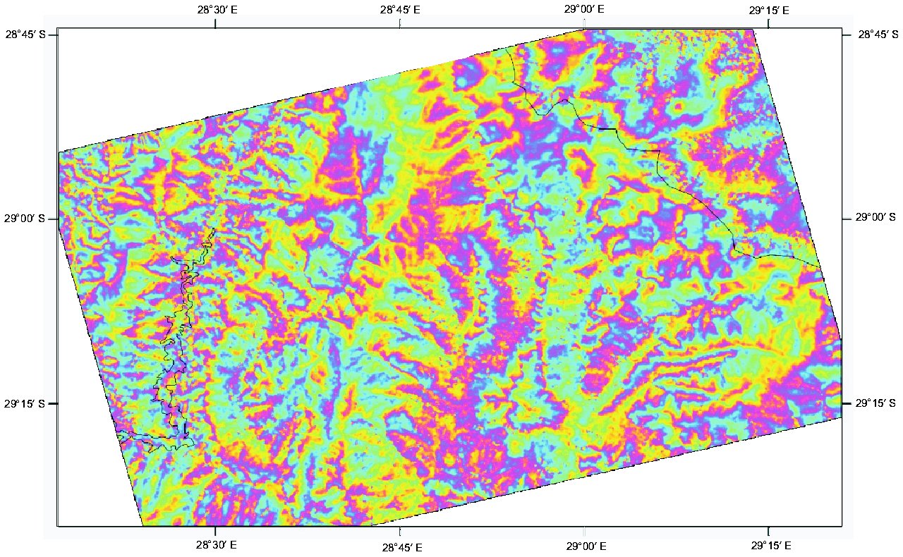
topographic fringes. Figure 6 shows a 3-year differential phase map with
residual topography of the Katse dam.
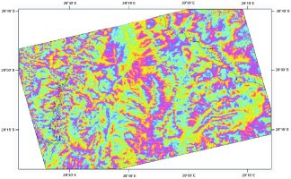
Figure 6: Katse dam 3-year differential phase with residual topography.
There are no apparent deformation fringes.
3.2 InSAR for Earthquake Mapping in South
Africa
Current work entails using differential InSAR to map the surface effect
of a recent earthquake in the gold fields of South Africa [26],
[29].
This Richter magnitude 4.2 seismic event, although possibly triggered by
mining activity, occured in a broad zone of infrequent natural seismicity.
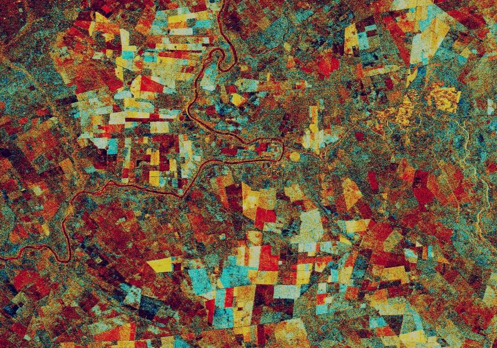
Figure 7 shows a false colour intensity composite of two ERS passes over
the Welkom goldfields. This area is not ideal for repeat pass interferometry,
since most of it is covered by active agricultural lands (see Figure 7).
The coherence is extremely low between passes, and therefore interferometry
may not be feasible at all.

Figure 7: False colour intensity composite of two ERS passes over
the Welkom goldfields.
3.3 Derivation of Digital Elevation Models
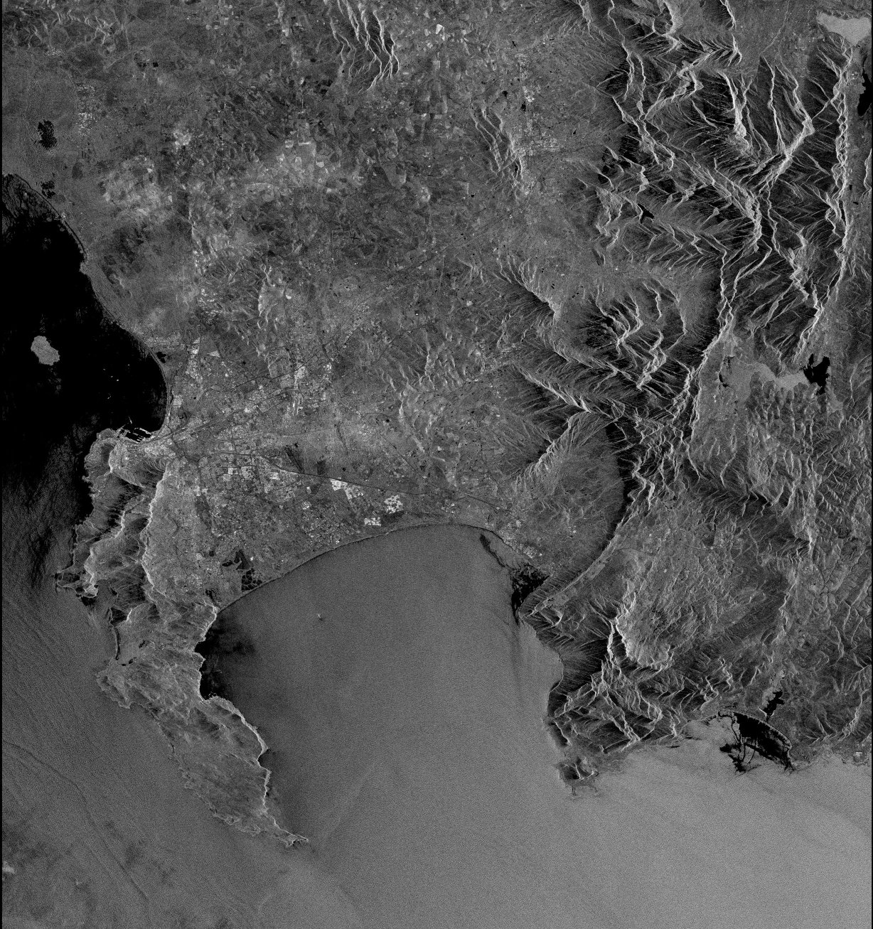
Tandem ERS data was used to derive a DEM of the Cape Town area. This turned
into a study of aberations found in single antenna interferometry [34].
We have attributed the aberations to atmospheric purturbations, or inconsistencies
between image acquisitions. Figure 8 displays an ERS multi-look intensity
image and the flattened interferogram of the Western Cape region.

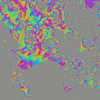
Figure 8: ERS multi-look intensity image and the flattened interferogram
of the Western Cape region.
4. Subsurface Radar Group
4.1 Hardware
The RRSG has been involved in ground penetrating radar (GPR) since
1990, and has developed a number of instruments, both pulsed and stepped-frequency
continuous wave (SFCW) types [8],
[19].
SFCW radars have the advantage of small size, low power and low cost. The
SFCW technique also lends itself to enhancing analogue to digital conversion
(ADC) performance through dithering and under-sampling. Some of the research
results can be viewed on line.

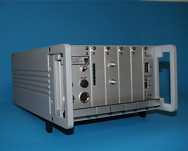
Figure 9: Mercury B GPR, developed by the RRSG. The radar electronics
are housed in a Eurocard enclosure, with external bowtie antennae. Shown
(left-to-right) are the power inputs, power supply, RF and IF cards.
Figure 9 shows a picture of the Mercury B GPR radar developed by the
RRSG. The current generation GPR, designated Mercury C, is configurable
with synthesizers covering the bands 50-400 MHz, 200-1600 MHz, or 800-3200
MHz. The radar is connected to a PC with fiber-optic cabling. The GPR under
development, Venus, contains ARM and PowerPC processor boards, and combined
with a touchpanel, will offer stand-alone capability. An innovative antenna
leakage cancellation scheme is under development. The group has sold more
than 8 systems to various industrial partners.
The RRSG is currently developing a SFCW borehole radar, for use in underground
tomography/interferometry. The radar is highly configurable and capable
of operation in SFCW or pulsed stepped-frequency modes.
4.2 Software
The current trend in software is distributed computing; this is implemented
in our radars by running a Common Object Request Broker Architecture
(CORBA) server on the radar itself. This maintains compatibility of the
data capture and processing software across different radar versions (with
on-the-fly configuration a goal), and even allows the Mercury GPR and borehole
radars to interface with the same software.
Work is currently being done on a new client-side distributed data aquisition
and processing system that will allow multiple users at different locations
to receive, view and process GPR data obtained from the radar. The system
will be modular, so that at run-time, a user need only link the particular
modules he requires for his purposes. This makes the system more configurable
to a wider variety of requirements. The advantage of this is that less
experienced users need not be subjected to an overwhelmingly large application
all at once, when they only require a small subset of its functionality.
A more experienced user is then able to view the data from a geographically
remote site, and process it according to his needs, or make adjustments
to the radar hardware across the network. This system is being developed
using Java and CORBA.
5. Multicomputer Technology Initiative
The Multicomputer Technology Initiative (MTI) project is a collaborative
venture between the RRSG and De Beers Consolidated Mines. The project is
funded by De Beers and the Department of Trade and Industry under their
THRIP program. In 1998, a decision was taken to investigate parallel computing
technologies using the ``pile of PCs'' approach. The reasons for this included
high performance/cost ratios, freedom from a single supplier and an easy
upgrade path. The emphasis has been on Beowulf-type systems and the technologies
available for these systems [9].
5.1 Hardware
The parallel cluster built at UCT, called Gollach, consists of 8 Pentium
II (350 MHz) PCs. Each node in the cluster is equipped with a standard
Intel 100 Mbps Fast EtherNet card. Initially, the nodes were connected
in a star configuration with an Intel 8-port hub. This provided an adequate
communications backplane for basic message passing, but did not have the
flexibility to cope with complicated inter-slave communications, full-duplex
or high throughput.
After a review of available inter-networking technologies (including
Gigabit EtherNet, ATM, Myrinet and Switched Fast EtherNet), it was decided
to upgrade the hub to a non-blocking Fast EtherNet switch capable of full-duplex
communications. This decision was taken on the basis of price/performance
ratio. The Cisco Catalyst switch has performed well and benchmark testing
has shown it to be capable of the advertised performance.
Some early results from Gollach are available on-line.
5.2 Software
The majority of the RRSG's work on the MTI has been done using the Linux
operating system. The MOSIX extensions to the Linux kernel produce a fully
distributed operating system capable of transparent process migration in
order to ensure full use of available system resources. MOSIX achieves
this through preemptive load balancing (migrating processes when a processor
load exceeds a threshold level) and memory ushering (migrating processes
to nodes with more available memory in order to avoid memory paging to
disk).
Messaging/communications software investigated included Parallel
Virtual Machine (PVM), Message Passing Interface (MPI) and Common
Object Request Broker Architecture (CORBA). Both PVM and MPI are message-passing
systems designed for use in parallel computing environments, while CORBA
has been designed as a portable, distributed computing backbone. XPVM,
an X-based monitoring tool for PVM, was installed, as well as Upshot, the
MPI equivalent.
5.3 Results
In order to test the working of PVM and MPI, some existing code for antenna
design using population based incremental learning (PBIL) was converted
to run on the cluster in parallel form. The results achieved with this
computationally intensive (i.e. not data-limited) code were promising.
Running on eight machines, a speedup of close to eight times was achieved
for this algorithm. It was observed that PVM was marginally faster than
the equivalent MPI implementation.
The chirp scaling algorithm was implemented on the Gollach cluster,
and very high speedup factors were achieved. At present, a patch range-Doppler
processor is being implemented [17].
6. Imaging Applications
A number of studies have been conducted in which SIR-C and traditional
optical and infra red imaging data have been evaluated for palaeodrainage
and general geological mapping in NW South Africa and Southern Namibia
[5].
Comparative studies have been conducted for purposes of geological mapping,
in which SIR-C and Landsat data were used both independently of one another,
and as integrated data sets. Figure 10 shows a SIR-C image of the Roter
Kamm meteorite impact crater in Namibia. Of particular interest was the
possibility of surface penetration of the dry sand in this region by the
SIR-C radar bands [1].
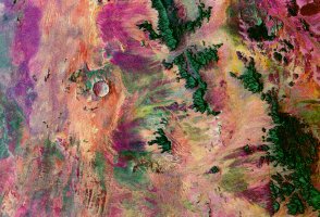
Figure 10: SIR-C image of the Roter Kamm meteorite impact crater
in Namibia.
Since both Landsat and SIR-C data was available for the Roter Kamm area,
this site was used for experimentation and validation of classification
methodologies. The studies have shown that radar imagery produces reasonable
classifications in relatively flat areas. To extend this to a site with
varied topography, a DEM is needed. It was also found that the choice of
speckle filter influenced the classification accuracies. Work is currently
in progress to obtain a speckle filter that optimizes classification accuracy
and reliability [2].
7. Aircraft and Ship Target Recognition
Aircraft recognition has been addressed by using synthetic range profiles
(SRPs) obtained from a stepped-frequency L-band search radar at the local
airport [20].
The system has been modified to operate over more than 100 MHz of bandwidth
and the down-range profiles are made after moving target indication
(MTI) processing. The RRSG has concentrated on the technology of producing
clean profiles which can be used by other researchers for the actual classification
and recognition process.
For ship target recognition, the group has concentrated on using low
resolution (12 m) downrange profiles taken with an X-band marine navigation
radar. These profiles are further analysed using Fourier-Mellin transformations
and neural networks. Good results have been achieved [28].
8. Other Projects
Over the years, numerous final-year, MSc and PhD students have contributed
to the accumulated expertise and knowledge of the RRSG. Some of the projects
that have been conducted include the following:
-
Stepped-Frequency Processing:
-
In order to increase the total radar bandwidth of a low-frequency SAR system,
such as the SASAR system, the use of stepped-frequency waveforms has been
thoroughly investigated [32].
It has also been shown how stepped-frequency processing can aid in suppressing
unwanted radio frequency interference [23].
-
Radar Simulator:
-
In conjunction with the non-cooperative target recognition (NCTR)
project described in Section 7, a radar simulator
was developed to produce synthetic range profiles of complex aircraft models,
which could then be used to investigate the feasibility of various aircraft-identification
algorithms [21],
[15].
It was then expanded and upgraded to generate simulated SAR data. Some
of the features of the radar simulator include chirp, monochrome and user-defined
pulse modulations, stepped-frequency implementation with constant or user-defined
frequency increments, independent moving platforms with user-defined paths,
angle dependent radar cross sections of point targets, rotating antennas,
spot mode SAR, point target and platform motion errors, and a powerful
image viewer.
-
Interferogram Simulator:
-
A software simulator for producing SAR images and interferometric products
has been developed [33].
The simulator requires a DEM, radar flight path information, receiver model
parameters, a terrain mask denoting terrain types for separate backscatter
models and a temporal decorellation mask. Outputs include a pair of registered
complex SAR images, an interferogram and layover and shadow maps in both
ground and slant range projections. Applications include mission planning
and algorithm testing, and it can also be used as a teaching tool for the
interferometric process.
-
DEM Retrieval via Multibaseline Interferometry:
-
Ongoing research aims at deriving a DEM via multibaseline interferometry
[22],
[4].
Multiple antennas in a single-pass configuration (eliminating time decorrelation)
are employed for multibaseline generation. This task is approached as an
inverse problem, and the solution is envisaged in a statistical setup based
on Bayesian estimation theory. As a further extension, incorporation of
a layover model [30]
(for accurate DEM reconstruction in steep areas) is being considered. Research
is currently progressing with encouraging intermediate results.
-
Wind-Vector Interpolation:
-
Dual swath satellite wind sensors are unable to obtain measurements directly
below the satellite, creating a ``nadir gap'' centered on the sub-satellite
track. Using processed ERS-1 wind field data, it has been shown that Ordinary
Kriging is an appropriate technique to interpolate this ``nadir gap'' [18].
-
In Situ Dielectric Properties Measurements:
-
A major problem for subsurface radars is to predict the true target distance
and maximum likely penetration depth in the media under investigation.
These radar parameters can be determined from the complex permittivity
of the media. Since the permittivity of the surface under examination is
usually unknown, most subsurface radars are calibrated in time units only;
actual subsurface distances have to be inferred from other knowledge of
the soil/rock. Work has been conducted to develop a technique which provides
on-line, complex permittivity measurements for the ground penetrating radar,
in order to help predict the important distance parameters [3].
The system consists of an electrically short monopole antenna backed by
a ground plane; the input impedance of the antenna is a function of the
complex permittivity of the surrounding media. Using a model for the complex
input impedance of the antenna, the electrical properties of the media
can be determined.
Acknowledgements
The author would like to express his thanks to all the current and past
members of the Radar Remote Sensing Group for their contributions toward
this paper. Special thanks go to R.T. Lord, G.S. Doyle, J.M. Horrell, A.J.
Wilkinson, A. Langman, M. Cope, A. Wallis and M. Gebhardt.
References
-
[1]
-
M.G. Abdelsalam, C. Robinson, F. El-Baz and R.J. Stern, ``Applications
of Orbital Imaging Radar for Geologic Studies in Arid Regions: The Saharan
Testimony,''
Photogrammetric Engineering & Remote Sensing, vol.
66, no. 6, pp. 717-726, June 2000.
-
[2]
-
L. Alexander and M.R. Inggs, ``An Investigation into the Effects of Speckle
Filters on Classification,'' Proc. IEEE Geosci. Remote Sensing Symp.,
IGARSS'99, Hamburg, Germany, June 1999.
-
[3]
-
N. Ballard, A. Langman and M.R. Inggs, ``On-Line Complex Permittivity Measurements
for Ground Penetrating Radar,'' Proc. IEEE Geosci. Remote Sensing Symp.,
IGARSS'94, Pasadena, USA, vol. 4, pp. 2513-2515, August 1994.
-
[4]
-
G. Corsini, M. Diani, F. Lombardini and G. Pinelli, ``Simulated Analysis
and Optimization of a Three Antenna Airborne InSAR System for Topographic
Mapping,`"
IEEE Trans. on Geosc. and Remote Sensing, vol. 37, no.
5, pp. 2518-2529, September 1999.
-
[5]
-
G.S. Doyle and M.R. Inggs, ``Dual Frequency Multi-Polarimetric SAR as a
Tool for Palaeo-Drainage Mapping in the Northern Cape Province,'' IEEE
Proc. of the South African Symp. on Communications and Signal Processing,
COMSIG'98, Cape Town, South Africa, pp. 339-342, September 1998.
-
[6]
-
G.S. Doyle, M.R. Inggs, C.J.H. Hartnady and E. Rignot, ``The Use of Interferometric
SAR in a Study of Reservoir Induced Crustal Deformation,'' Proc. European
Conference on Synthetic Aperture Radar, EUSAR'98, Friedrichshafen,
Germany, pp. 95-98, May 1998.
-
[7]
-
G.S. Doyle, A.J. Wilkinson and M.R. Inggs, ``Contending with High Relief
and Temporal Decorrelation in an InSAR Study of the Effects of Reservoir
Loading,''
Proc. IEEE Geosci. Remote Sensing Symp., IGARSS'99, Hamburg,
Germany, June 1999.
-
[8]
-
G. Farquharson, A. Langman and M.R. Inggs, ``A 50-800 MHz Stepped Frequency,
Continuous Wave, Ground Penetrating Radar,'' IEEE Proc. of the South
African Symp. on Communications and Signal Processing, COMSIG'98, Cape
Town, South Africa, pp. 455-460, September 1998.
-
[9]
-
M. Gebhardt and M.R. Inggs, ``The Multicomputer Technology Initiative at
UCT,''
AFRICON'99, vol. 1, pp. 589-592, September 1999.
-
[10]
-
J.M. Horrell, ``An Extension to Range-Doppler SAR Processing to Accommodate
Severe Range Curvature,'' Proc. IEEE Geosci. Remote Sensing Symp., IGARSS'99,
Hamburg, Germany, June 1999.
-
[11]
-
J.M. Horrell, ``Range-Doppler Synthetic Aperture Radar Processing at VHF
Frequencies,'' PhD thesis, University of Cape Town, Private Bag, Rondebosch
7701, South Africa, May 1999.
-
[12]
-
J.M. Horrell and M.R. Inggs, ``Airborne Flight Path Reconstruction for
VHF SAR Signal Processing,'' Proc. 3rd European Conference on Synthetic
Aperture Radar, EUSAR2000, Munich, Germany, pp. 161-164, May 2000.
-
[13]
-
J.M. Horrell and M.R. Inggs, ``Range Curvature Limitation of the Range-Doppler
Algorithm Stripmap SAR Processing,'' Proc. European Conference on Synthetic
Aperture Radar, EUSAR'98, Friedrichshafen, Germany, pp. 99-102, May
1998.
-
[14]
-
J.M. Horrell and M.R. Inggs, ``Semi Desert and Forest Measurements using
the South African VHF SAR System,'' Proc. 3rd European Conference on
Synthetic Aperture Radar, EUSAR2000, Munich, Germany, pp. 145-148,
May 2000.
-
[15]
-
M.R. Inggs, ``Radar Computer Simulator Optimised for SAR Work,'' Proc.
3rd European Conference on Synthetic Aperture Radar, EUSAR2000, Munich,
Germany, pp. 457-460, May 2000.
-
[16]
-
M.R. Inggs, ``The SASAR VHF Sensor,'' Proc. European Conference on Synthetic
Aperture Radar, EUSAR'96, Königswinter, Germany, pp. 317-320,
March 1996.
-
[17]
-
M.R. Inggs, M. Gebhardt and G. Pollock, ``Beowulf Computational Techniques
Applied to SAR Processing,'' Proc. 3rd European Conference on Synthetic
Aperture Radar, EUSAR2000, Munich, Germany, pp. 189-192, May 2000.
-
[18]
-
M.R. Inggs and R.T. Lord, ``Interpolating Satellite Derived Wind Field
Data Using Ordinary Kriging, with Application to the Nadir Gap,'' IEEE
Trans. on Geosc. and Remote Sensing, vol. 34, no. 1, pp. 250-256, January
1996.
-
[19]
-
A. Langman and M.R. Inggs, ``New Technology UWB Stepped CW Radar,'' Proc.
of the PIERS workshop on Advances in Radar Methods, July 1998.
-
[20]
-
R. Lengenfelder, ``NCTR Phase VIII: Aircraft Data Capture and Analysis
Report,'' Technical report, University of Cape Town, Private Bag, Rondebosch
7701, South Africa, March 1998.
-
[21]
-
R. Lengenfelder, ``The Design and Implementation of a Radar Simulator,''
MSc. dissertation, University of Cape Town, Private Bag, Rondebosch 7701,
South Africa, November 1998.
-
[22]
-
F. Lombardini, ``Absolute Phase Retrieval in a Three Element Synthetic
Aperture Radar Interferometer,`" Proc. CIE Int. Conf. Radar, Beijing,
China, pp. 309-312, October 1996.
-
[23]
-
R.T. Lord, ``Aspects of Stepped-Frequency SAR Processing at VHF Band,''
PhD thesis, University of Cape Town, Private Bag, Rondebosch 7701, South
Africa, February 2000.
-
[24]
-
R.T. Lord and M.R. Inggs, ``Efficient RFI Suppression in SAR Using LMS
Adaptive Filter Integrated with Range/Doppler Algorithm,'' Electronics
Letters, vol. 35, no. 8, pp. 629-630, April 1999.
-
[25]
-
D. Massonnet and K.L. Feigl, ``Radar Interferometry and its Application
to Changes in the Earth's Surface,'' Reviews of Geophysics, vol.
36, no. 4, pp. 441-500, 1998.
-
[26]
-
D. Massonnet, M. Rossi, C. Carmona, F. Adragna, G. Peltzer, K.L. Feigl
and T. Rabaute, ``The Displacement Field of the Landers Earthquake Mapped
by Radar Interferometry,'' Nature, vol. 364, pp. 138-142, July 1993.
-
[27]
-
Radar Remote Sensing Group at the University of Cape Town: http://www.rrsg.uct.ac.za/
-
[28]
-
A.D. Robinson and M.R. Inggs, ``Ship Target Recognition using Low Resolution
Radar and Neural Networks,'' Trans. IEEE AES, vol. 35, no. 2, pp.
386-393, April 1999.
-
[29]
-
R. Stow, D. Reddish, P. Wright, G.S. Doyle, A.J. Wilkinson and M.R. Inggs,
``Geotechnical Applications of SAR Interferometry,'' ESA FRINGE Meeting,
pp. 1-8, 1999.
-
[30]
-
A.J. Wilkinson, ``Synthetic Aperture Radar Interferometry: A Model for
the Joint Statistics in Layover Areas,`" IEEE Proc. of the South African
Symp. on Communications and Signal Processing, COMSIG'98, Cape Town,
South Africa, pp. 333-338, September 1998.
-
[31]
-
A.J. Wilkinson, J.M. Horrell and M.R. Inggs, ``SASAR VHF Interferometry:
Early
Results,'' Proc. 3rd European Conference on Synthetic Aperture Radar,
EUSAR2000, Munich, Germany, pp. 411-414, May 2000.
-
[32]
-
A.J. Wilkinson, R.T. Lord and M.R. Inggs, ``Stepped-Frequency Processing
by Reconstruction of Target Reflectiviy Spectrum,'' IEEE Proc. of the
South African Symp. on Communications and Signal Processing, COMSIG'98,
Cape Town, South Africa, pp. 101-104, September 1998.
-
[33]
-
L.S. Wray, A.J. Wilkinson and M.R. Inggs, ``Synthetic Aperture Radar Image
Simulator for Interferometry,'' 28th International Symp. on Remote Sensing
of Environment, ISRSE, Cape Town, South Africa, March 2000.
-
[34]
-
H.A. Zebker, P.A. Rosen and S. Hensley, ``Atmospheric Effects in Interferometric
Synthetic Aperture Radar Surface Deformation and Topographic Maps,'' Journal
of Geophysical Research, vol. 102, no. B4, pp. 7547-7563, April 1997.
Return to RRSG Homepage
Last updated 24th July 2000 (RTL).